
In many applications, regulation of the air flow to a specified setpoint offers the possibility of significantly reducing energy consumption and noise emissions (Fig. 1). First of all, this applies to the fan itself; in many applications such as air-conditioning systems, this also has a positive effect on the energy requirements of other system components such as heaters, coolers or humidifiers. In addition, application-specific and regional legal requirements must often be complied with, e.g. for ventilation of residential buildings.
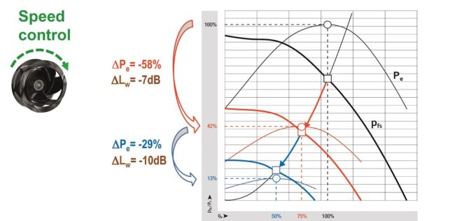
Figure 1: Demand-based adjustment of the air flow enables significant energy savings and noise reduction. (Photo: ebm-papst)
Specifications for residential buildings
For example, DIN 18017-3 applies to exhaust fans in windowless bathrooms and toilets. According to this, the exhaust air flow may change by a maximum of 15% at a pressure difference of +/-40 Pa or +/-60 Pa. In individual ventilation systems with a common exhaust air line, a reduction in the exhaust air flow of the lowest unit of a maximum of 10% is permitted when operating all units. This is intended to ensure that the exhaust air flow changes as little as possible in the event of external wind forces acting on the building envelope.
There are similar legal requirements for decentralized ventilation of individual rooms or for central residential ventilation units with heat recovery. DIN EN 13141-8 applies to decentralized systems. Here, the units are divided into three quality classes depending on the resulting change in air flow at a pressure difference of +/-20 Pa (Fig. 2).
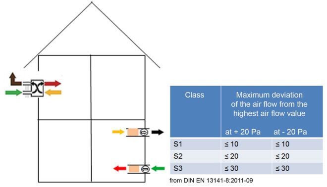
Figure 2: Specifications in DIN EN 13141-8 for decentralized ventilation systems with heat recovery. (Photo: ebm-papst)
In the case of central ventilation systems, the exhaust air flow must always be higher than the intake air flow according to the DIBT approval (German Institute for Construction Technology), but the excess exhaust air may not exceed 10%. Satisfactory values can only be achieved here if the air flow of the fans used in the application can be precisely determined and regulated as needed by adjusting the speed.
Methods compared
In principle, there is wide range of physical measuring methods for determining a volume or mass flow rate; however, not all of them are suitable for gases and therefore for fans. Magnetic-inductive measuring methods or those based on Coriolis force are ruled out, for example, as they only work with electrically conductive media or the forces generated with gases are much too small. Mass flow measuring methods with thermal sensors are, in principle, suitable for fans, but only under laboratory conditions, as the thin measuring wires are very sensitive.
Not all measuring methods that are possible in principle do not necessarily turn out to be practical.
Other measuring methods are highly accurate and robust, but relatively expensive to implement and therefore more suitable for test rigs. On an ultrasonic flow meter, two offset detectors record the transit-time difference of two ultrasonic waves proportional to the average flow speed (Fig. 3).
Alternatively, flow speeds can be recorded using a vane anemometer or using a vortex generator according to the vortex principle (Fig. 3). On a vortex generator, the shedding frequency of the vortices proportional to the flow speed is detected. In the case of the anemometer, the speed and air flow are proportional.
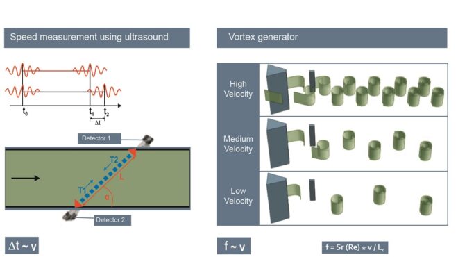
Figure 3: Left: speed measurement using ultrasound; right: vortex generator. (Photo: ebm-papst)
What is practical?
Things that are possible in principle do not necessarily turn out to be practical. Speed measurements can be used in the inflow or outflow of a fan in all fan types and the relatively small sensors do not cause any relevant pressure losses. In many applications, however, the additional costs for the sensors, their installation, and the effects of aging or contamination present substantial obstacles.
In addition, flow speeds measured “locally” – i.e. in one place – require precise knowledge of the operating point or installation-dependent speed distribution in the cross-sectional area through which the flow passes or corresponding unit-specific calibration to determine the air flow.
The measuring accuracy at low air flows is significantly reduced by the pressure drop or pressure difference methods.
On the other hand, volume flow control systems based on measuring the pressure drop or pressure difference are now found relatively frequently in air conditioning systems or ventilation units (Fig. 4). A sensor is also required here for pressure measurement. However, in many cases the measuring points can be applied in such a way that the speed is not measured purely locally, but instead that enables at least an approximate “integral” measurement of the air flow to be taken via the pressure signal.
In addition, there are normally no additional pressure losses and the processes are relatively independent of the inflow and outflow and the operating point. The greatest disadvantage of the pressure drop or pressure difference methods is that the measuring accuracy at low air flows is significantly reduced by the quadratic relationship between air flow and pressure. In addition, there are application-specific problems: for example, if the pressure difference across a heat exchanger or filter is used in a residential ventilation unit, the measuring signal is heavily dependent on contamination and bypass flows.
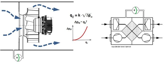
Figure 4: Left: pressure difference measurement at the inlet nozzle of a centrifugal impeller in an air conditioning system; right: pressure drop measurement in a residential ventilation unit. (Photo: ebm-papst)
Sensorless control
If there is a clear relationship between power consumption and air flow at a constant speed, an operating point can be determined by measuring the motor current and the speed. These characteristic curves are only found for forward-curved centrifugal impellers. The term “sensorless” control is often used in the context of electronically commutated blowers because only internal motor variables are used and no external pressure or speed sensors are required.
Various ebm-papst blowers use sensorless control integrated into the electronics for constant volume control (Fig. 5). To determine the operating point, this relies on a blower-specific and, in some cases, also unit-specific calibration polynomial. However, the relationship between power consumption and air performance which is cubic in the first approximation leads to significantly increasing control inaccuracies, even in this approach at low air performances. In addition, a change in the air density results in an error in air flow determination.
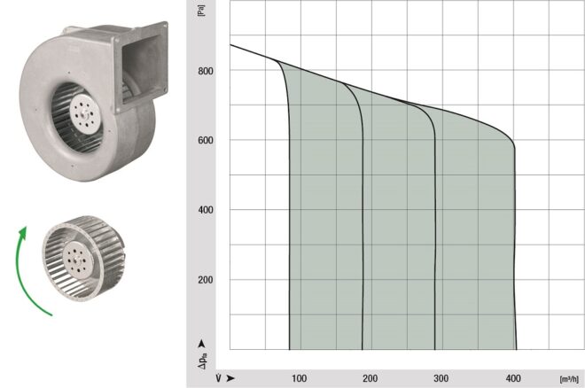
Figure 5: Sensorless constant volume control of a forward-curved ebm-papst centrifugal fan. (Photo: ebm-papst)
Efficient solution for backward-curved centrifugal fans
In the case of backward-curved centrifugal fans, sensorless air flow determination is not possible due to their characteristic curve. For this highly efficient fan design, the flow specialists at ebm-papst have developed a ready-to-install plug & play solution: a vane anemometer positioned in the outlet nozzle of the scroll housing (Fig. 6). It continuously records the actual air flow without significant pressure losses or additional noise. The data is transferred to the integrated central control electronics of the fan.
This adjusts the speed of the EC motor to the desired setpoint and regulates the air volume of the blower to the specified setpoint regardless of air density influences. As the speed of the vane anemometer is no longer quadratically, but only linearly dependent on the air flow and the speed of the EC motor is used as an additional internal correction variable, very high control accuracy can still be achieved even with low air flows. In addition, determination of the operating point is barely negatively affected by the effects of installation through recording the entire air flow.
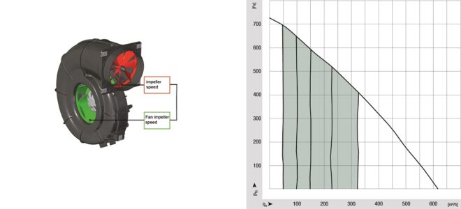
Figure 6: Constant volume control of a backward-curved ebm-papst centrifugal fan with vane anemometer. (Photo: ebm-papst)
With this very robust and fully integrated constant volume control, an extremely precise and efficient solution can be achieved over the entire control range. For residential ventilation units, this means, for example, balanced supply and exhaust air flows all year round. On the one hand, this prevents the unwanted supply of cold outside air; on the other hand, this prevents warm room air flowing outwards in winter through leaks through the building envelope, cooling down and thus creating condensation in the outer walls.
The additional impeller does not result in any air performance losses or disruptive noise, meaning that the overall performance of the fan remains unchanged. Even contamination is not a problem, as has been demonstrated in tests under extreme conditions with dust and increased air humidity.
Leave a comment