Numerical aerodynamics and simulation are part of day-to-day development work for motor and fan manufacturer ebm-papst. For many years, its engineers have been working on developing their fans using powerful CFD tools, not only for optimizing complex impeller geometries (Fig. 1), but also for motor or electronics cooling concepts or in the context of acoustic testing for noise characteristics. Customers benefit from this extensive expertise and from the aerodynamic design of their own end devices that are going to contain ebm-papst fans.

Fig. 1: CFD simulation is used to continually improve the impeller geometry of the fans – for greater efficiency and better air flow. (Image | ebm-papst)
Potential simulation in the product development process
The simulation of fluid mechanics makes flow and flow variables such as pressure or velocity visible in the entire calculated area. In terms of measurement, it is often not possible to measure at certain points or, under certain circumstances, the measuring instruments influence the flow, or a variety of measuring sensors and methods are required to obtain comparable information. The measuring set-up that results is then complex and expensive. In addition, a sample device that can be measured must have been set up beforehand. If an unfavorable flow situation is then found in the device during such tests, this can often only be implemented with a successor product as part of a redesign for time and cost reasons.
That is why it is better to simulate the installation situation for aerodynamics in the early development phases of a customer device. This facilitates a flexible response to aerodynamic weaknesses in the design because the customer’s digital prototype can be optimized before a first sample is actually set up. The calculation result of the actual state forms the basis for assessing the quality of adapted design variants.
This ensures at an early stage that the installed fan really works with the desired properties without high costs accumulating. It is therefore worth taking advantage of the possibilities of CFD at an early stage of development. (Fig. 2).
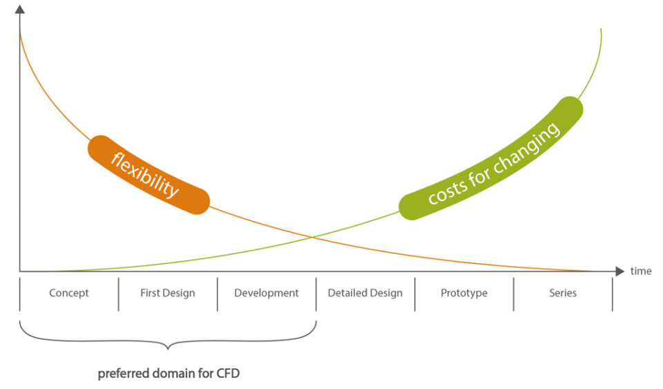
Fig. 2: Ideally, the simulation is used at the beginning of a project as far as possible so that solutions can be assessed at an early stage. (Image | ebm-papst)
Simulation as a service
CFD can be used to calculate, visualize and improve the flow conditions in the customer device, or to compare different concepts with one another. The fan’s energy consumption and sound depends on how the housing encourages air flow, whether it is drawn in axially from the front, centrifugally from all sides or on one side. In poor cases, this can double the power consumption or halve the efficiency, and can significantly increase the noise level. CFD helps in understanding the aerodynamic conditions in the device (Fig. 3).
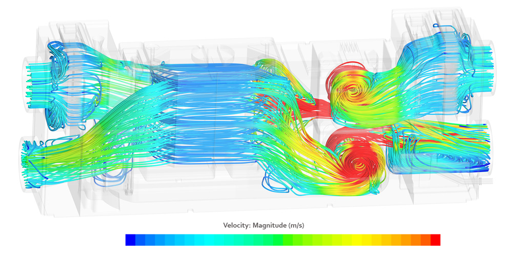
Fig. 3: Visualization of air flow through a ventilation unit. (Image | ebm-papst)
Before the simulation begins, the objective should first be defined and a few questions answered. Does air have to flow through a heat exchanger as evenly as possible? Is the simulation supposed to detect pressure losses? Does the customer want to perform a general check on the choice of fan? Is the device in which the fan operates supposed to be as quiet as possible? Once these types of questions have been clarified, the 3D CAD data and the expected operating point (pressure, air flow, speed) of the fan provide the basis for simulation. In addition, there are also characteristic curves from the filters, heat exchangers or guard grills installed in the device, for example. The data are cleared up and unnecessary details are removed (cleaning). Then the simulation is prepared in a preprocessing phase, meaning that certain boundary conditions are specified and the geometries are networked. The grid structure divides the space that the air passes through into many individual cells, which form the basis of the mathematical calculation. The simulations then run on high-performance computers that are in a server room at the ebm-papst site in Hollenbach.
Practical examples: Exploiting potential for optimization
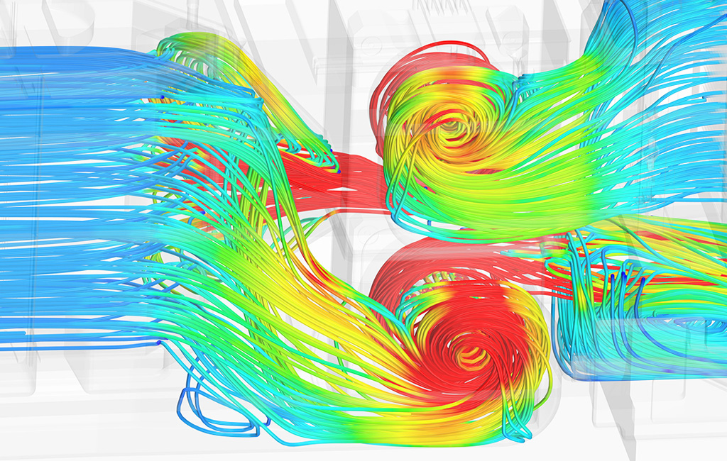
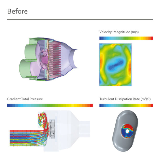
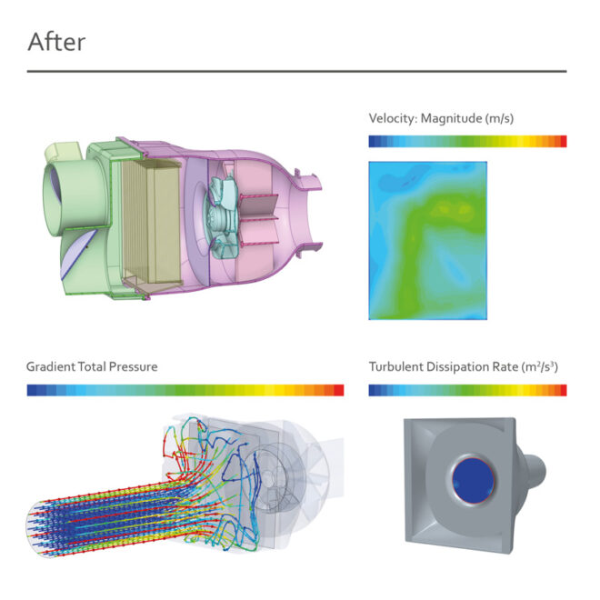
Using the simulation results, the engineers then estimate the potential for optimization and develop concrete suggestions for improvement. For example, a customer developed an air purification device in which the fan was to be used for pushing air out. However, the simulation showed significant turbulence (Fig. 4), which increased the power consumption at the operating point. Using the fan to draw air in, i.e. changing its installation position, proved to be helpful here. The air flow is now very uniform, the power consumption is decreased and there is also a positive effect on operating noise.
Another example: Using simulation results, the efficiency of a heat pump could be significantly improved. Thanks to geometric changes, the pressure losses in the device fell by a total of 17 percent. The individual sub-areas in the device were assessed separately and the product design was adapted accordingly. Here too, the user benefited from the opportunities provided by CFD calculation.
These examples show that it is worthwhile for end device manufacturers to rely on numerical flow simulation and to apply these at an early stage of development to avoid subsequent development costs. ebm-papst supports this with its long-standing CFD experience and offers such evaluations and calculations to ensure that the fans operate as efficiently as possible in the application. Even small optimizations to the installation situation can reduce pressure losses, increase efficiency, or minimize running noise.
Leave a comment