
If there were only one type of gas in the world, life would be much easier for heater manufacturers. They would need to configure their combustion system just once to provide the optimum gas and air mixture ratio, after which the condensing boiler would provide heat equally efficiently in all parts of the world – leaving aside ambient parameters such as temperature or air pressure for now.
However, natural gas is produced by a natural process, and it has a different heating value depending on where it comes from. In the Netherlands and Germany, for example, L-gas is traditionally used. Its name reflects the fact that it is low-calorific (L = low). This contrasts with H-gas from Russia, which has a higher methane and thus energy content, making it high-calorific (H = high). Since sources are running dry and the market is changing, there are also new fuels such as liquefied gas from the USA, as well as synthetic gas or hydrogen from power-to-gas plants. Therefore, finely balanced systems are required to set the optimum combustion mixture.
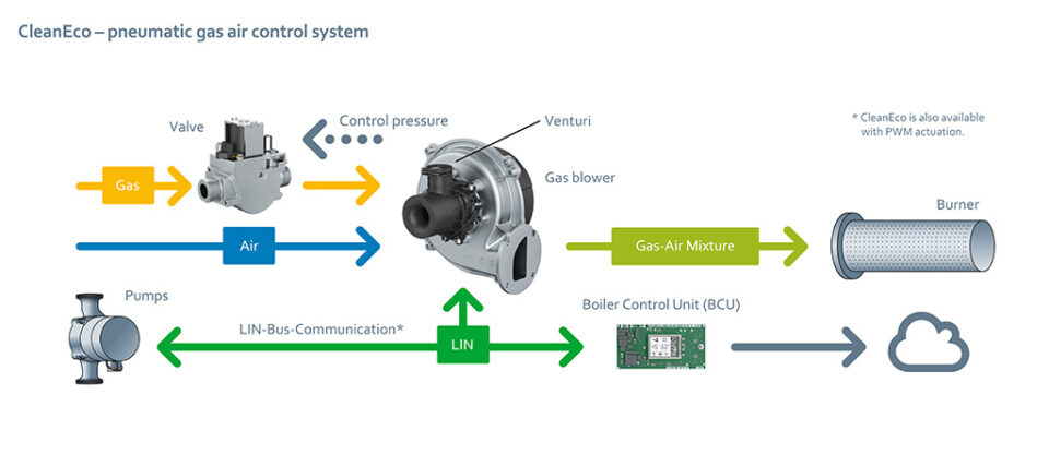
Fig. 1a: The interaction between all components is a decisive factor for both electronic and pneumatic networks. The gas valve plays an important role here in ensuring the correct combustion mixture. (Graphic | ebm-papst)
Key role within the network
In practice, pneumatic combustion control has proven its worth in this regard for many years. As a result of fluctuations in gas quality, electronic combustion control is gaining in importance as an alternative. ebm-papst offers both variants as a complete solution under the names CleanEco (pneumatic, Fig. 1a) and CleanVario (electronic, Fig. 1b).
Within these systems, the gas valve plays a key role. Firstly, it prevents the gas from flowing out in an uncontrolled manner, and secondly, it only allows the exact quantity that needs to be mixed with the air to flow through. The important thing is to ensure a coordinated approach with the blower, venturi, and control unit. That works best when all components come from a single source. This is why ebm-papst has also included gas valves in its range since 2011 and is continuously expanding and refining the range, such that four power classes (Fig. 2 and 3) in the range 1.5 – 762 kW can now be offered.

Fig. 1b: The interaction between all components is a decisive factor for both electronic and pneumatic networks. The gas valve plays an important role here in ensuring the correct combustion mixture. (Graphic | ebm-papst)
The classic solution: the D01 valve
Mechanical valves are used in pneumatic networks. Their operating principle is that if the thermostat in the home switches on or if someone turns on the hot water faucet, the boiler starts working. The blower rotates as per the required power, the gas valve is opened, and the taper in the venturi causes a vacuum that draws in the gas. In simple terms, the faster the blower rotates, the more gas is taken in. This must not happen in an uncontrolled manner. Therefore, the valve should only open until it allows the exact quantity for the combustion mixture to pass through.
How does this work? A look at the interior of valve D01 from ebm-papst provides the answer (Fig. 4). There are two safety valves on the gas inlet side. If one fails, the other can still prevent an uncontrolled supply of gas. The safety valves are lifted by way of electromagnetic coils and the gas can flow in. The operating valve is located on the outlet side, which is connected to the venturi. The vacuum generated by the blower exerts a force via a working diaphragm. This force mechanically lifts the operating valve.
Two adjusting screws can be used to regulate the extent of this action: the offset and main flow throttle setting. The offset (shifting the zero point) can be set on the servo controller. The offset pressure is always regulated to zero, regardless of the suction pressure generated by the premixing blower. This also enables pressure fluctuations in the supply network to be compensated. The throttle element adjusts the quantity of gas required based on the gas quality. For example, with L-gas a larger quantity flows through than with H-gas. This means that both settings are crucial for ensuring a correct gas-air mixture ratio over the entire modulation range.
The D01 valve is the first one that ebm-papst included in its product range and is suitable for a very wide power range of 8 to 120 kW. Thanks to its compact dimensions, the D01 is a space-saving solution for integration into the boiler.

Fig. 2: The gas valve range from ebm-papst for pneumatic networks. (Graphic | ebm-papst)
Low power, big impact: the E01 valves
For lower power classes of up to 81 kW, the engineers at ebm-papst have further refined the D01 principle and provided an even more compact solution: the E01 valve. The crucial difference lies in the design of the safety valves. Instead of being distributed across two coils, they are combined in a single module. This uses less material and also saves more energy as there is only one coil that has to be energized. The E01 is available in two versions: for power ranges from 1.5 to 57 kW and 3 to 81 kW.
More flexibility: the F01 valve
The gas valve is becoming much more important in electronic networks. Here, the mixing ratio is not controlled by the vacuum but by the electronic actuation of the gas valve. Instead of reacting passively, it thus actively controls the gas supply. This means that, in contrast to pneumatic networks, the valve does not have to be manually set in advance to suit the respective gas type and quality, as the system adapts to the gas.
The valve needs a parameter to ensure it knows how much gas it should provide for mixing with the air. ebm-papst relies on what is known as ionization technology for this, which uses the electrical conductivity of the flame. If a voltage is applied, the so-called ionization current can be measured directly in the flame using an electrode. This can be used to draw conclusions about the combustion quality: If the current is too weak, the valve receives the signal to supply more gas; if it is too high, it restricts it.

Fig. 3: The gas valve range from ebm-papst for electronic networks. (Graphic | ebm-papst)
To ensure that the gas valve can actively control the gas supply, it has to be designed differently than in a pneumatic network. With the F01 series, ebm-papst offers the ideal valves for all power classes between 1.8 and 762 kW (see Fig. 3). In terms of the safety technology, the developers relied on the same system as for the E01. However, a stepper motor with integrated pressure regulator is used on the outlet side. This motor can precisely vary the flow rate and, in turn, the amount of gas.
If the flame sends the signal that combustion is not optimal, this patented solution can take the appropriate countermeasures flexibly. This means that, in an electronic network, it almost doesn’t matter which fuel is flowing through the pipes. What’s more, the manufacturers have to worry much less about the different gas types and qualities – the combustion is always optimal, efficient, and environmentally friendly.
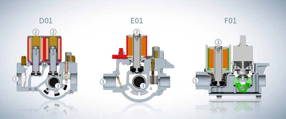
Fig. 4: All three gas valve types from ebm-papst shown as sectional views. The gas flows in from the left (1). The two safety valves (2) are opened by one (E01, F01) or two (D01) electromagnetic coil(s). In the D01 and E01, the operating valve (3) is used to regulate the pressure and quantity. (Graphic | ebm-papst)
Three valves with a whole host of benefits
The D01 valve
• Compact dimensions mean greater flexibility for manufacturers
• Easy access to electrical connections and settings
• Precise adjustment of the gas-air ratio using the offset and main flow throttle setting
The E01 valve
• This makes it even smaller and allows for low electrical power
• Produced in ever-increasing volumes since 2014
• Easy access to the connections
• High offset accuracy and thus optimum compensation of pressure fluctuations in the supply network
The F01 valve
• Patented solution comprising stepper motor and integrated pressure regulator
• Optimized design enables fully automatic mounting
• Very precise control in a power range of 1.8-762 kW
• Modular design enables the valve to be optimally combined with other system components
The perfect combination
Whether it’s a pneumatic or electronic network, it is crucial that all components in a combustion system are perfectly coordinated with one another. This means that the blower and valve have to be a good match. ebm-papst offers the following possible combinations:
| Blower | Gas valve |
| RadiMix VG 71 & VG 100 | E01 and G15 F01 |
| RadiMix VG 108 | G20 D01 and G32 F01 |
| VG 145 | G20 D01 and G32 F01 |
| RG 175 | G32 F01 and G40 F01 |
| G1G 170 | G40 F01 |
| G3G 200 | G40 F01 |
Leave a comment