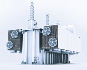
Transformers generate waste heat when they are in operation and oil is the coolant of choice. It transfers the heat through convection (or supported by pump systems) to the transformer housing, which has cooling fins or radiators similar to heat exchangers on the outside. Large high-power transformers require additional cooling: fans that prevent damage from overheating despite cooling surfaces that are as compact as possible (Fig. 1). The fans have to satisfy special requirements so they can withstand harsh outdoor deployment conditions.
Fans turn transformers into energy savers
It isn’t enough for fans to support the required air performance. Properties such as corrosion resistance even in high humidity, no-maintenance operation without lubrication, and reliable functioning over as long a service life as possible are just as important. And when loads fluctuate, it is also beneficial when the cooling capacity can adjust to actual demand. It does not always make sense to switch off individual fans when the transformer is in partial-load operation because in this state, uncooled “hot spots” can arise on the heat exchanger.
If the fans are operating as efficiently as possible, over the years, users can save significant amounts of money and power, which they can feed into the electricity grid. This results in a positive economic benefit for energy operators. If the transformers are near or even in residential areas, the noise they generate plays a role that should not be underestimated either.
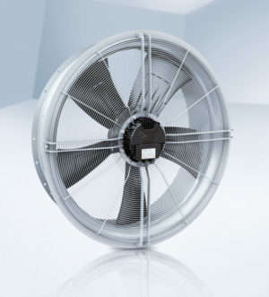
ebm-papst Mulfingen, the motor and fan specialist, has addressed this issue by developing special transformer fans (Fig. 2). They satisfy all the requirements for sophisticated large transformer cooling as per DIN EN 50216-12 “Power transformer and reactor fittings – Part 12: Fans” and come in sizes 500 mm to 1,250 mm with air performance of up to 13 m³/s.
Their development is based on decades of experience and intense research supported by extensive simulations and tests. They also satisfy special requirements with regard to long service life and salt spray resistance (corrosion protection class C5M as per DIN EN ISO 12944), so the fans are suitable for deployment in coastal areas with high salt contents.
Fan housing increases fan efficiency

All the components of the plug-&-play-compatible modules – the fan housing, HyBlade® impeller, EC motor with integrated electronics or AC asynchronous motor and intake-side guard grille – are perfectly harmonized. For example, aerodynamic optimization reduces both air turbulence and operating noise. The two motor types satisfy the requirements of the current ecodesign directive.
The impeller has an aerodynamically ideal form based on combining an aluminum frame with a covering of glass-fiber-reinforced plastic. This reduces the noise it produces dramatically, enabling higher efficiency in comparison to traditional blades. The motor mount, which also has a contact protection function, is installed on the intake side. On the outlet side, a guard grille is also available as an accessory.
If the fans are operating as efficiently as possible, over the years, users can save significant amounts of money and power.
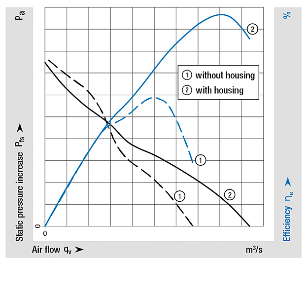
Both the guard grille and the fan housing are made of hot-dip galvanized sheet steel with an extra coating. The outlet side also has an integrated circumferential flange for direct attachment to the radiator. Especially when the fans function with free air (as usual in the case of oil-cooled transformers), the positive effect of this type of fan housing is excellent (Fig. 3). It keeps air turbulence to a minimum, increasing the airflow rate and therefore, fan efficiency (Fig. 4).
Speed control for needs-based cooling
Companies that rely on proven EC technology are taking one more step in the direction of energy efficiency. EC motors are basically synchronous motors with permanent magnet excitement. In them, a rotor with integrated permanent magnets synchronously follows the rotating field of the stator, which is generated electronically. The control electronics enable infinitely adjustable air performance (linear to the fan speed), which deviates from the grid-synchronous frequency in partial-load operation at practically the same high level of efficiency. The open-loop speed control can either be specified analog via 0-10 VDE (e.g. oil temperature or oil pressure sensor) or digitally with a PWM or MODBUS signal. When MODBUS is used, several fans can be conveniently interconnected. This facilitates the use of diagnostics and monitoring functions, which ultimately contribute to reliable operation. This set up means the entire system can be operated more economically and has a positive effect on the life cycle costs.
Companies that rely on proven EC technology are taking one more step in the direction of energy efficiency.
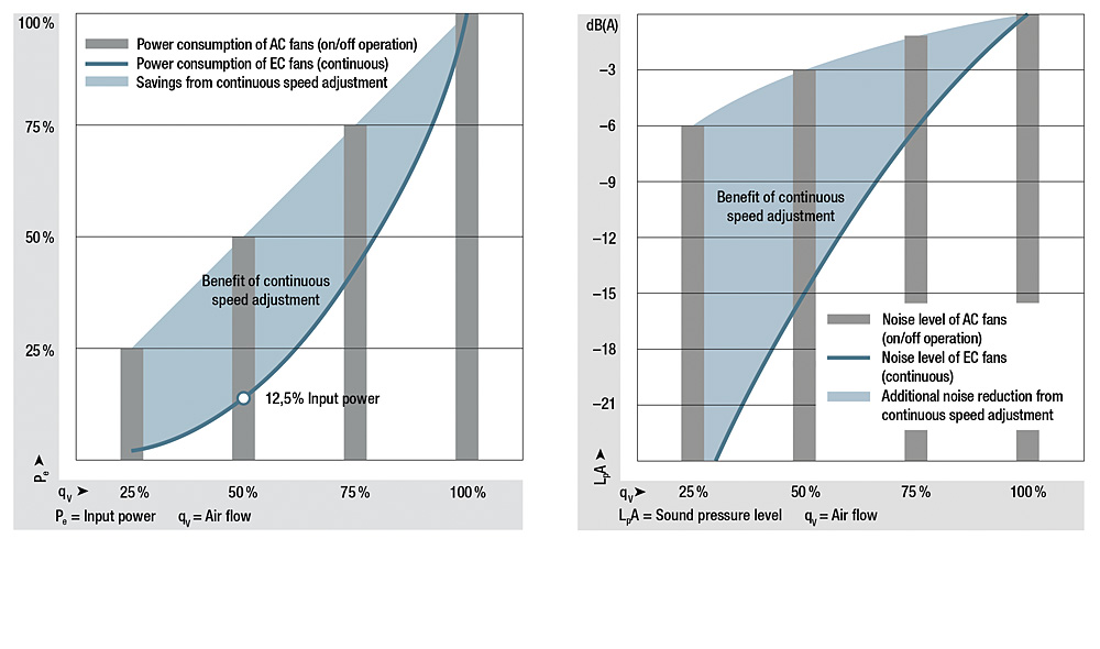
To prevent hot spots on the heat exchanger after individual fans have been switched off, ebm-papst recommends using all fans in partial-load operation. The consequence is a more even flow through the radiator. A positive side effect: the motor does not heat up as dramatically, which extends the fan’s service life. Another aspect of partial-load operation is the high reduction in energy consumption and operation noise as a result of the physical laws. The electrical input power is proportional to the fan speed to the third power (Pe ~ n³). As a result, it is only 12.5 % when the speed and in turn, the air performance, are reduced by 50 %. Logarithmically, this reduces the noise level by 15 dB (Fig. 5).
Partial-load operation not only saves energy and lowers operating costs, but also results in less waste heat. This is especially valuable for cooling applications because heat that is not generated does not need to be dissipated. Commutation and the stator design also ensure very smooth operation. The cycle frequencies are acoustically imperceptible and noise reduction drops. This makes these “stealth fans” ideal for applications in which the noise protection regulations must be observed.
Simple commissioning and worldwide use
Practice-oriented design details simplify transformer fan commissioning. For example, it is possible to install and mount directly on the fan housing with a horizontal or vertical installation position as required. The motor terminal box for supply connection and control is easily accessible and isolated from the motor electronics. The development team made a point of using high-quality terminals. The fans are perfectly designed for worldwide use. They function on power supplies between 200 -240 V and 380 - 480 V (for 3-phase 50 Hz and 60 Hz grid frequencies), satisfy all the relevant standards (UL, CSA, EAC and CCC) and the requirements of degree of protection IP55, and the rating label satisfies DIN EN 50216-12 (“Power transformer and reactor fittings” – Part 12: Fans).
Leave a comment