
The world badly needs energy-saving solutions; from lighting right through to electrical drive systems. Even simply adapting the speed of drive systems to the actual torque/power requirements saves on unnecessary power consumption. The use of efficient EC motors also taps into additional potential for savings, which benefits the environment and the operator’s running costs in equal measure. However, this very welcome development has a catch: The input currents of the new energy-saving devices – which are generally phase-shifted and pulsed as opposed to sinusoidal – incur additional losses in the generators, cables and transformers of the power supply. The reactive power caused by the phase shift and harmonic currents must be made available. This becomes an unwanted cost factor, particularly in such isolated networks as the ones found in data centers. A solution needs to be found for this issue.

Circuit feedback caused by current harmonics
The power supply of a data center essentially consists of a grid infeed transformer, UPS system and a standby generator (Fig. 1). Together, these components must ensure a reliable power supply (through the principle of redundancy). On the other hand, the provision of additional reactive power requires all components involved in the power supply to deliver higher performance. Unnecessary over-dimensioning of this kind is undesirable because of the associated costs.

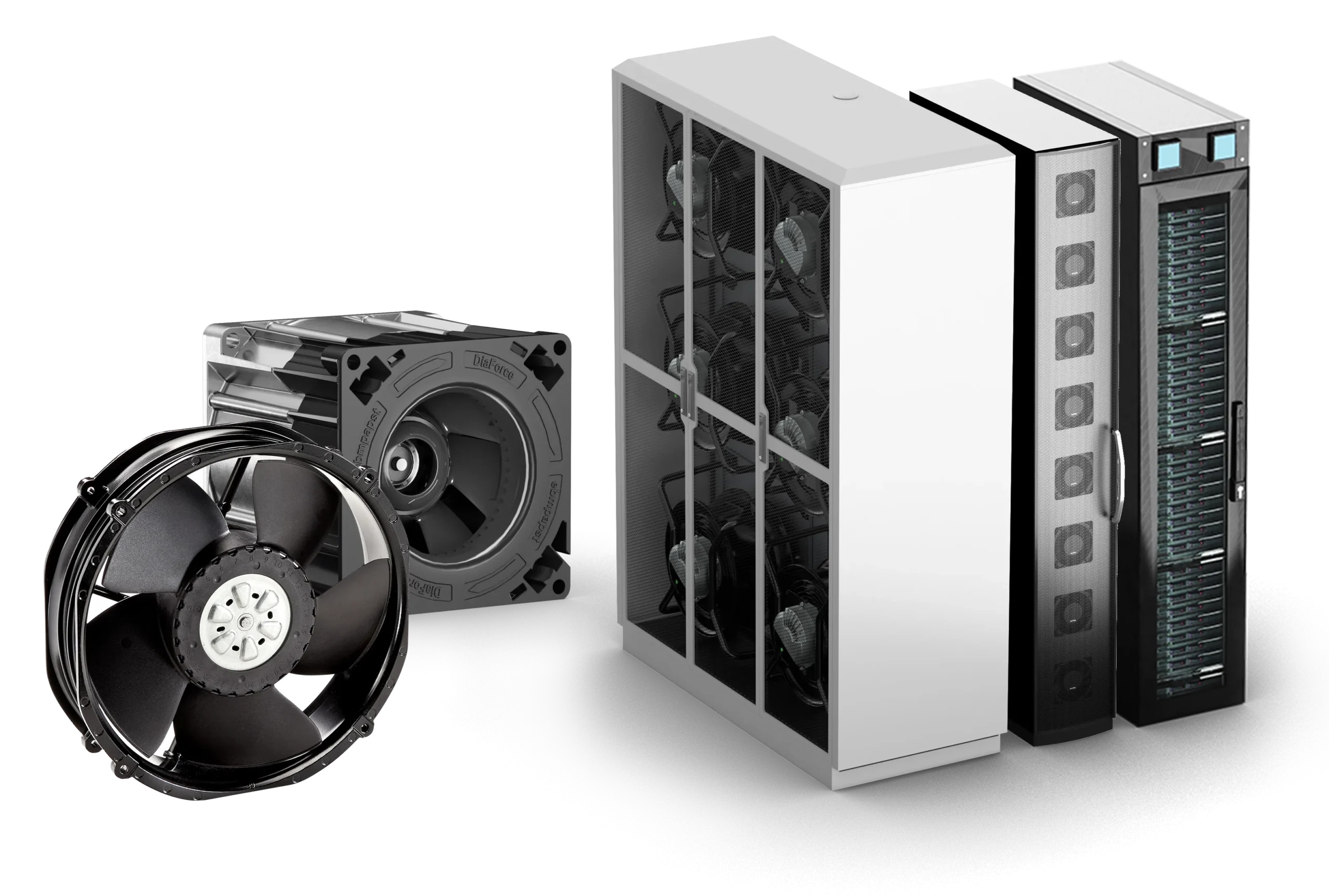
High performance, low carbon:
ebm-papst reimagines data center cooling. Our efficient cooling solutions combine energy efficiency with high power density.
However, as is the case for asynchronous motors with variable-frequency drives, power-consumption-optimized EC fans now have a pulsed – as opposed to sinusoidal – current draw due to their circuitry, yet without needing additional measures. Every departure from a sinusoidal current draw brings about current harmonics, which largely lead to what is known as “distortion reactive power”. This puts additional strain on the supply network and leads to increased losses in all components involved in the power supply.

By way of an example, Fig. 2 shows the input current of a server cooling system with two fans arranged in parallel, each of which has a power consumption of approx. 3 kW. At 6.69 kVA, the reactive power is above the effective power of 5.74 kW in this case. The power factor, i.e. the quotient of effective power to apparent power, is a poor 0.64, while the total harmonic distortion (THD(I)) of the current is around 120%. This means that the geometric sum of all harmonic currents is larger than the fundamental component itself. It is easy to conceive how such currents might place a significant strain on all components required in the power supply chain, i.e. transformers, the UPS system, generators, and even cables. The distortion reactive power must be maintained at the infeed point. In the interest of optimizing the power supply and backup system, the current distortion should be as low as possible. In other words, the power factor should be close to a value of 1.
(Video | ebm-papst)
Regulatory Standards for Harmonic Currents in Three-Phase Equipment
The values stipulated by standard EN 61000-3-2, which applies to conventional industrial systems, are insufficient in this case. This standard classifies devices with a phase current of up to 16 A and defines harmonic-current limit values for these classes. Fans fall within equipment group A, which contains household appliances alongside symmetrical, three-phase devices, for example.

Power quality under control – no extra effort required!
Discover in the white paper how integrated active rectification makes EC fans ready for the toughest requirements.
The higher the input currents become, the more difficult it is to adhere to the limit values of Class A because these are absolute limit values (i.e. not relative to the respective output) defined for the individual classifications of the harmonic spectrum. Only active filter solutions can be of help from a certain input current level. For three-phase devices, however, these are extremely intricate and not economically attractive for “normal” industrial applications. This is perhaps the reason why three-phase devices with outputs of over 1 kW are not covered by the standard. As a result, there are simply no limit values at all for three-phase devices with outputs of between 1 kW and approx. 10 kW. On the other hand, if multiple devices for which no limit values apply as individual devices are interconnected, and if the phase current is in a range of between 16 A and 75 A, an additional standard applies: EN 61000-3-12 defines the limit values for individual classifications of the harmonic spectrum and the total harmonic distortion of the current. The interesting aspect of this is that the permissible values are dependent on the grid quality. The “softer” the grids are – that is to say, the higher the complex internal resistance of the grid is – the lower the limit values for the harmonic content of the current will be. This is only logical: After all, a non-linear current distorts the voltage waveform more significantly as the internal resistance of the grid increases. In order to satisfy demands in this case, measures also need to be taken for classic variable-frequency drives with a three-phase supply. Because a low level of internal resistance can usually be assumed in most industrial grids, a limit value of 48% applies for the harmonic content in accordance with EN 61000-3-12.
Line chokes and DC-link chokes only help to a certain extent
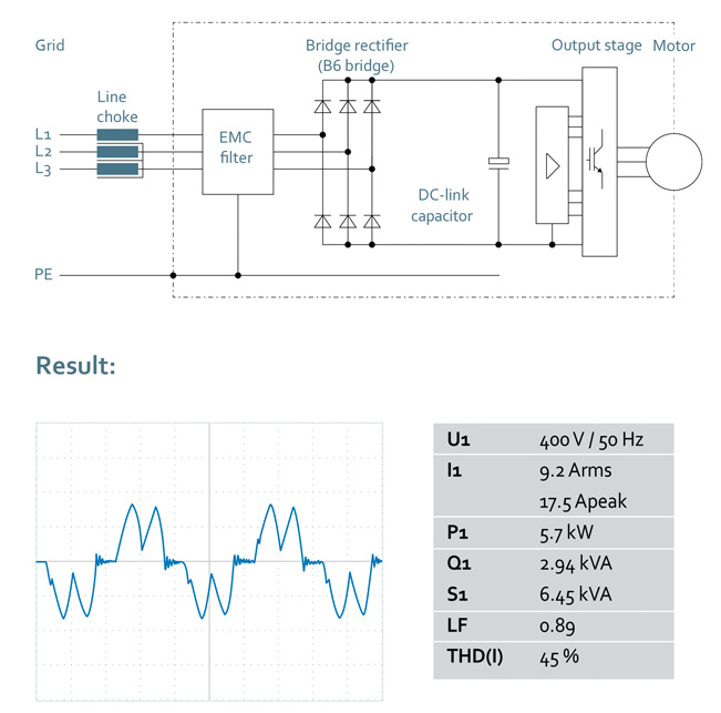
This value, which still falls well short of satisfying the needs of today’s data centers, can be achieved with relative ease, such as by installing a line choke upstream (Fig. 3). Nonetheless, such chokes require space and additional cabling. For the example mentioned above featuring 2 fans, each rated at approx. 3 kW, values of around 0.9 and 45% can be achieved for the power factor and total harmonic distortion (THD(I)) respectively with a 2% line choke.
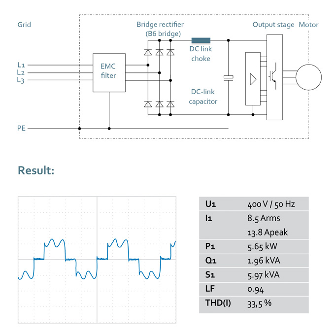
Even better values can be achieved if a DC-link choke (Fig. 4) is incorporated into the power electronics (which is a standard feature of ebm-papst EC fans with a three-phase supply and highly capacitive DC link): The requirements of standard EN61000-3-12 are satisfied with a power factor of approx. 0.94 and a THD of 34%, at least as far as the limit values for “hard” (i.e. low-impedance) industrial networks are concerned. However, in cases where the grid voltage distortions are problematic and/or grid impedance levels are high, the harmonic content in the current must be reduced to a minimum. Consequently, target values of over 0.95 for the power factor and a THD(I) of below 5% are now frequently stipulated for many data-center applications.
The target value for THD(I) is below 5%
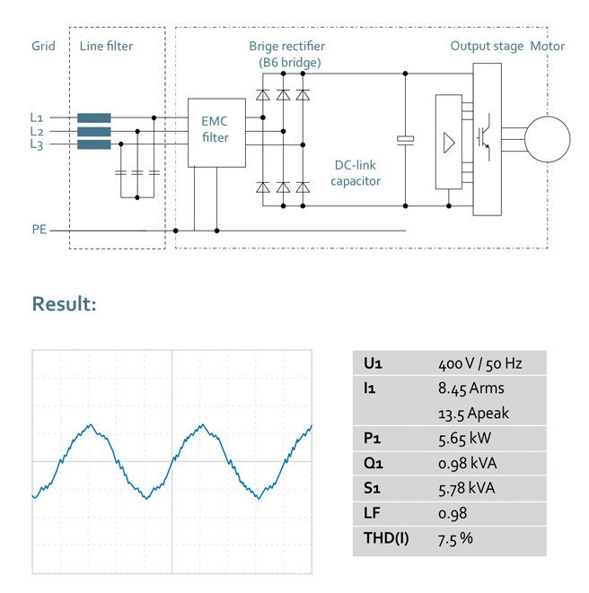
Ballast solutions in the form of harmonic filters (Fig. 5) are one theoretical option for approaching such values. These filters are quite impressive with regard to their characteristics and the quality of materials used – a fact which is also reflected in the price tag. Nonetheless, the achievable values do come very close to hitting the target: In the example here, a power factor value of 0.98 and a harmonic content of 7.5% in the phase current are achieved, while the current waveform is more or less sinusoidal.
Despite their benefits, such filters often have the drawback of only being optimally designed for one single operating point that generally corresponds to the rated output. In partial-load operation, the THD(I) values are often twice as high. The power factor also diminishes at lower output levels. As a result, the reactive currents become very high in partial-load operation. What is more, there is a considerable voltage drop through the filter; the nominal speeds and output values of the fans might not actually be reached under certain conditions.
The disadvantages of passive filters can be largely avoided by employing an active filter solution. Ballast devices are available in this case, although these are also more expensive and require additional space and wiring effort.
Problems caused by harmonic currents
- Overloading of neutral conductors
- Overheating of transformers
- Nuisance tripping of (miniature) circuit breakers
- Harmonic resonance
- Skin effects
- Signal interference
Active PFC in fans as a plug & play solution
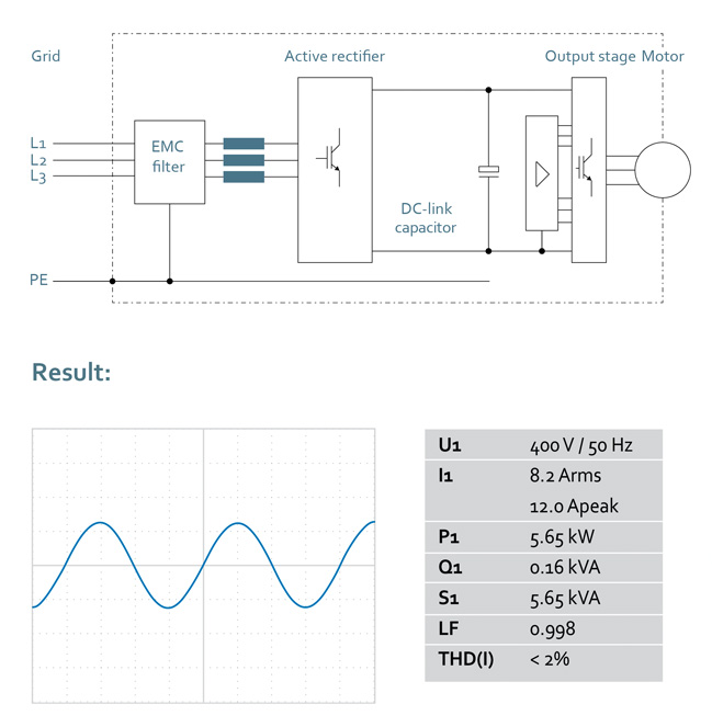
With this in mind, the motor and fan specialists at ebm-papst have made the fan manufacturer the first to incorporate a three-phase, active PFC stage into their EC fans in the form of an active rectifier with the aim of saving the user additional effort (Fig. 6). This overhaul started with motor size 150 (3 kW), which can be found installed in the new RadiPac fan sizes 450, 500, and 560, in addition to RadiCal fan sizes 500, 560, and 630. The values which can be achieved actually exceed requirements: With a power factor of over 0.99 under the rated load, the THD(I) value is typically around 2%. The THD(I) value even stays below 5% all the way down to 10% of the rated output.
In the axial direction, the motors are only slightly longer due to the integration of the three-phase active PFC, while the loss of efficiency at the rated output is low at around 2%. Not only that, but the operator still enjoys the advantage of having the pulsed input current of the EC motors found in conventional solutions converted to a sinusoidal input current without needing to wire in additional components and without filters and motors needing to be matched to one another. The highly efficient, plug & play-capable EC fans reduce energy consumption in data centers while also granting the wish of only having to design the power supply of such systems for the rated effective power of the fans.
Problems caused by harmonic voltages
- Voltage distortion/voltage overshoots
- Overheating and starting problems with induction motors
- Zero crossing problems
RadiPac Centrifugal Fans with Active Power Factor Correction (PFC)

The latest generation of RadiPac centrifugal fans is equipped as standard with EC motors featuring integrated electronics that include active power factor correction (PFC). This ensures that power consumption is particularly smooth and gentle on the grid—an essential advantage in sensitive environments with stringent requirements for power quality. Thanks to active PFC, the power factor is significantly improved, minimizing harmonic distortion and ensuring compliance with international standards such as EN 61000-3-2. The integrated control circuitry regulates current draw so that it remains in phase with the line voltage, thereby reducing reactive power and improving overall system efficiency. Combined with aerodynamically optimized impellers, compact design, and high power density, RadiPac fans offer a highly efficient solution for demanding data center applications.
Leave a comment