Vibration is omnipresent. While some kinds of vibration are perceived as pleasant, such as music, others can cause major damage. This is because resonance may occur if a system is excited periodically by a force whose excitation frequency matches a natural frequency of the system. In this state, vibration amplitudes increase sharply. Although the attenuation effects that are always present limit the amplitudes within the resonance, low attenuation and high excitation force will cause the vibration amplitudes to increase very significantly to the point that they may exceed the system’s load limit.
The excessive oscillation then results in damage, especially if this state is maintained over a prolonged period of time. For example, vibrations may loosen screw connections or damage ball and roller bearings. Even buildings can be damaged if they are excited with the resonant frequency, which can then lead to what is known as a resonance catastrophe. That is precisely what happened when the Tacoma Narrows Bridge collapsed in 1940 after being excited into oscillation by unusual wind conditions just a few months after it was opened.
„Excessive oscillation over a prolonged period of time result in damage. Small vibration amplitudes that are not critical in mechanical terms may cause unpleasant noise.“
Bernhard Siedler, Head of Product Management at ebm-papst Mulfingen
However, resonances do not always result in system failure. Even small vibration amplitudes that are not critical in mechanical terms may cause noise that is perceived as unpleasant. This must also be avoided.
Excitation sources
Vibration excitation cannot be avoided completely and has different causes: internal and external excitation.The most critical internal excitation is the 1st order excitation (speed) caused by a rotor imbalance. Balancing reduces this excitation to a non-critical level but can never eliminate it entirely. Any rotating mass has a residual imbalance. During operation, the imbalance may be worsened by dirt on the impeller. Incorrect handling of a fan (impact during transportation, rolling it on its impeller) can cause plastic deformation, increasing the imbalance and, as a result, the excitation forces.
Higher-frequency excitation also occurs, such as blade passing noise (e.g. 5th order excitation in a fan with five blades) or cogging torque (e.g. 12th order excitation in a 12-slot motor). In ebm-papst products, these excitations are optimized and reduced to a minimum. External excitation may be broadband – like the wind that caused the Tacoma Narrows Bridge failure or flow-induced vibration resulting from unfavorable installation conditions (insufficient distance between the impeller and wall) – or it may have a specific frequency such as the motor speed of a compressor installed close by. This can also excite natural frequencies, resulting in resonance.
The installation conditions affect the resonance behavior
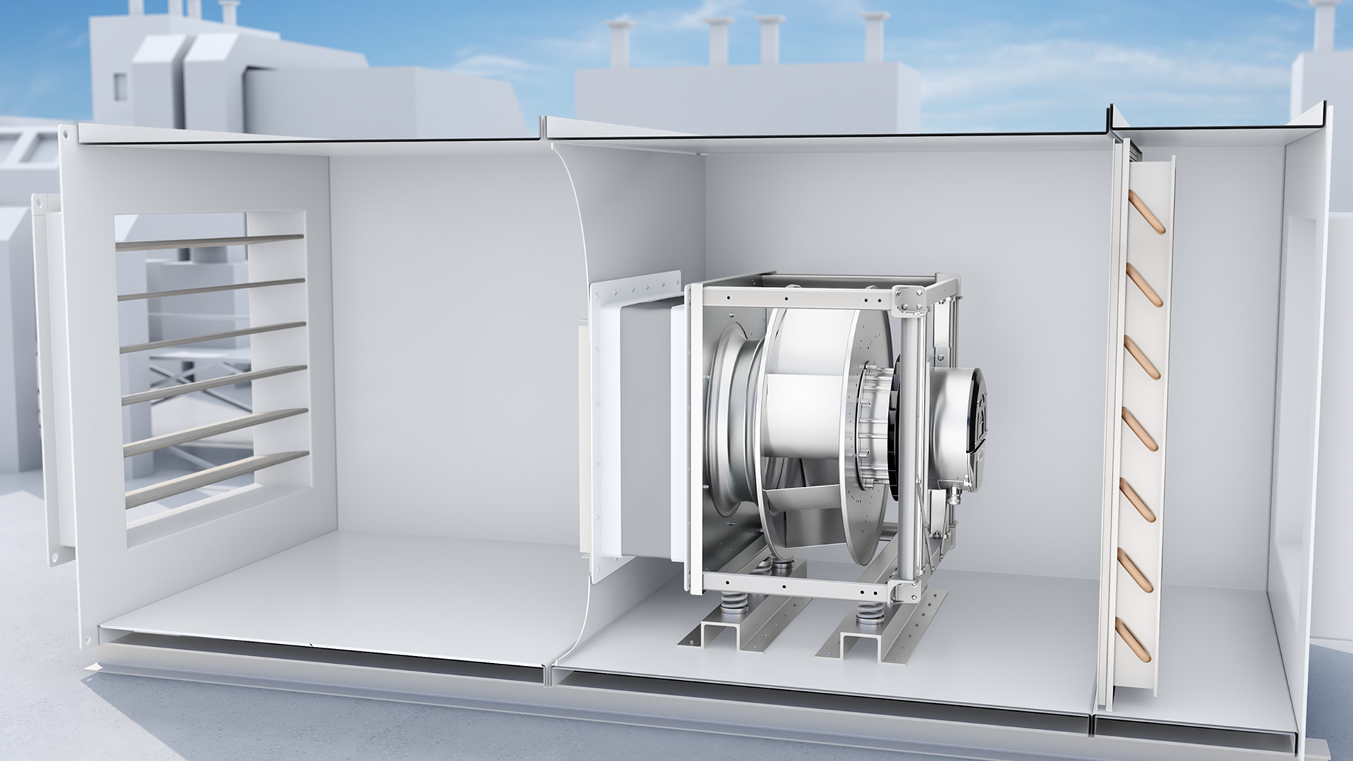
As each system has one or more natural frequencies, fans are also not immune to resonance-related damage, despite being balanced precisely by the manufacturers during production in accordance with the state of the art. A crucial role is played by the conditions of a fan’s installation, which unfortunately can neither be predicted nor allowed for in advance. Installing a fan in a system always creates a new resonant arrangement with several specific natural frequencies (Fig. 1).
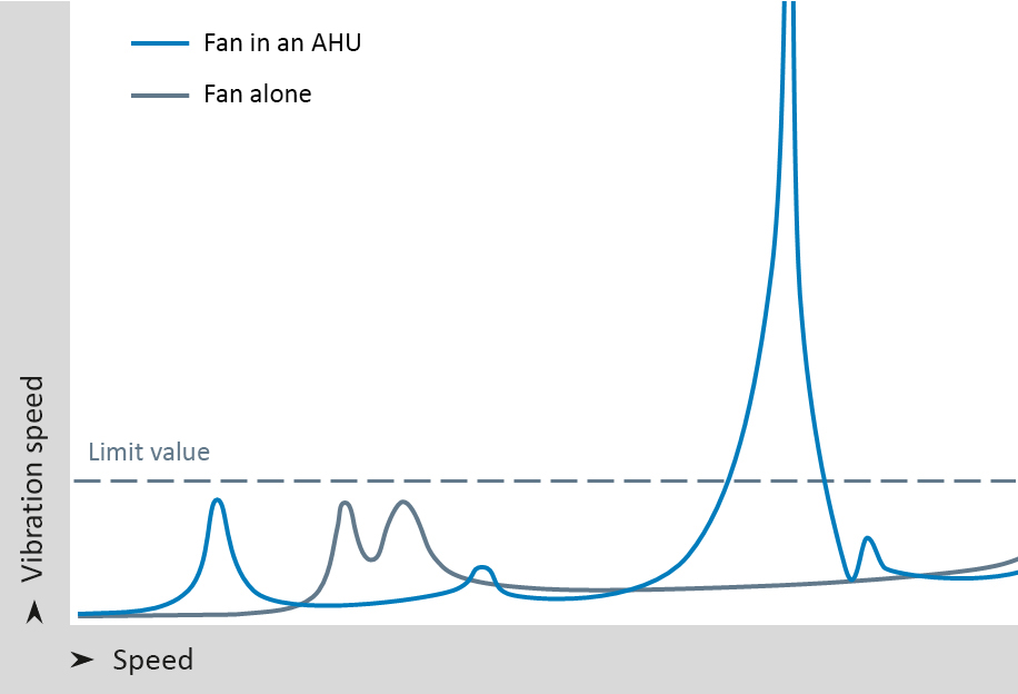
With the speed-controlled operation that is now widespread, the likelihood that a fan will at times be operated at resonance increases considerably. The reciprocal effects are often underestimated. Here, the resonant system consisting of a fan and its surroundings can lead to a considerable shift in the natural frequencies of the overall structure, thus resulting in a significant increase in the dynamic loads caused by resonance.
However, the influences of the surrounding structures can be simulated very precisely using FEM and the location of the critical speeds can then be predicted if the application design is known. By stiffening the correct structural components, resonance points can be shifted to a less critical range or even eliminated completely from the excitation (no resonance).
Vibration measurement in the installed state
It is therefore necessary to test the resonance characteristics of the fans during operation and in interaction with the surroundings, modifying them if necessary. This involves determining the vibration levels and avoiding speed ranges at which vibrations exceed the limit value. It is also necessary to identify the resonance speeds and ensure that these are not sustained during normal operation. Following the installation of a fan, vibration measurements and/or a search for resonance points should therefore be performed throughout the entire speed control range.

This provides an overall impression of the system’s vibration characteristics and reveals any unpredictable effects and also possible mistakes made during the run-up to commissioning. These resonance points must also be monitored during operation, at least within the interval specified in the operating instructions. This is usually every six months because natural frequencies may shift during service life, for example, if the rigidity of the customer’s system changes. Of course, acoustic changes are always a warning sign, but damage is usually unavoidable by that stage.
Rules for vibration measurement
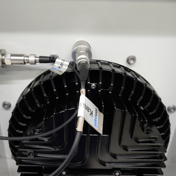
A number of aspects must be considered in vibration measurement. The first is avoiding disruption to the air intake system, i.e. there must be enough space in front of the impeller to ensure unobstructed air flow. For the vibration analysis of centrifugal fans, ebm-papst recommends measuring vibration in all three axes (Figs. 2 and 3), but at least in two axes – radial and axial to the axis of rotation – using a typical vibration measuring unit fitted close to the motor mount. This provides the effective value of the vibration speed (mm/s) but does not automatically identify potentially critical speeds.
To do this, the fan must be operated at various speeds and data recorded, for example, by logging in an external device. In the simplest case, the speeds are noted in a table, indicating where resonant frequencies occur. The best approach is to increase the speed by 5% increments, for example. The start-up time can also play a role. The best approach is a linear start-up, with the speed increasing from minimum to maximum over a five-minute period.
Automatic resonance detection for more operational reliability
To make it easier to handle unavoidable resonance, the third generation of centrifugal fans with integrated high-performance electronics from ebm-papst is equipped with automatic resonance detection. The integrated vibration sensors detect the speeds at which resonance occurs and the associated software prevents operation in the specified critical ranges.
For this purpose, a test start-up can be performed during commissioning in which the vibration speed is analyzed over the entire speed progression from standstill to nominal speed (Fig. 4). If excessive vibration speeds are detected in certain ranges, the control software adjusts itself after activation by the customer so that these speed ranges are “passed over” in the future. This means that the fan passes through these speeds, but continuous operation in these ranges is avoided. Operators can manually edit the software settings at any time, meaning that they always have full control.

Fig. 4: Vibration behavior with barred speed range. (Image | ebm-papst)

Fig. 5: Vibration characteristics in the AHU with additional external vibration source, e.g. a compressor. (Image | ebm-papst)
However, the vibration speed may also increase during operation, for example due to dirt deposits on the impeller, which results in additional imbalances. In this case, the software emits an automatic warning. The operator can now check the system for additional imbalances and can perform troubleshooting measures (e.g. cleaning and/or new start-up). Vibrations that are introduced by devices installed nearby, e.g. defective compressors, can be detected but not avoided. In this case, the operator can initiate suitable measures (Fig. 5). This makes automatic resonance detection a useful option for increasing the operational reliability of the centrifugal fans in critical applications.
Side note: Vibration-absorbing elements and speed range
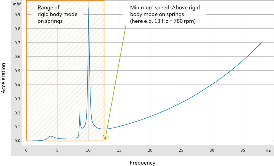
Vibration-absorbing elements (Fig. 6), such as apptopriately designed springs or rubber elements, help to isolate fans from vibrations in their surroundings (and vice versa). However, certain aspects must be taken into consideration when selecting these elements. Alongside the natural frequency of the fan set-up itself, the installation of vibration-absorbing elements produces a further spring-mass system with its own resonant frequency. The fan moves as a rigid body on the vibration-absorbing elements (fan deformation is negligible).

In this case, the movement comes from deformation of the vibration-absorbing elements, which also causes higher vibration amplitudes. For this reason, the fan may only be operated above rigid body mode, which determines the minimum speed (Fig. 7). Although the device does not suffer any direct damage during operation in rigid body mode, prolonged operation in this range reduces the overall service life. It can also result in high noise levels. This speed range should therefore be passed through as quickly as possible, and sustained operation in this range avoided altogether.
The speed range in which the vibration level is much lower begins at a sufficient distance from the resonance peak. Only in this range, above the minimum speed, can the vibration-absorbing elements isolate the fan from the vibrations of the system or building. To select the right vibration-absorbing elements, the operating speed of the fan in its application must be known.
For every fan, one can find correctly sized vibration-absorbing elements and the associated minimum speed. The above-mentioned factors must be heeded if using different elements. It is always worth considering vibration-related aspects when installing fans. Correctly installed fans function reliably throughout their service lives, unexpected failures are prevented, and users also benefit from lower noise emissions.
Leave a comment