For refrigeration and cooling equipment, the heat generated in the circulation process has to be transferred to the ambient air via a heat exchanger. To accomplish this, fans move cool air through a heat exchanger and allow the heat to dissipate. There is a whole range of options for designing and configuring especially efficient, quiet and durable fans. A new, passive component, the so-called diffuser, provides for a substantial improvement in efficiency and noise. Its pressure-boosting effect minimises exit losses and makes it easier to adapt the fan to commercially available heat exchangers.
Ventilation and air-conditioning units usually run in continuous operation, or at least with long operating cycles. That make maximum economy with the input drive energy important, for every additional watt costs money and impacts the environment. For that reason, energy efficiency is an important criterion when choosing a fan. Today, statutory stipulations also play a role. The efficient use of energy and resources is and will remain a global objective for the decades ahead. In Europe, the first tier of the ErP Directive became effective as of January 1, 2013. Against this background, it is no wonder that ultra-efficient EC technology is increasingly replacing conventional AC technology as the fan drive of choice due to its greater efficiency.
Exit losses – the underestimated “energy guzzlers”

Figure 1: Power flow of an axial fan with unimpeded airflow
Energy-efficient and quiet operation of the complete fan is a function of both the motor and the impeller, which the fan uses to move the air volume needed to create the cooling air flow through the heat exchanger. Aerodynamic expertise is needed when designing the impeller, for example to avoid separations and backflows which would cause both energy loss and unwanted noise. Even today, the impellers employed in the EC fans satisfy the most demanding standards. But there is another point which has to be taken into account when considering the efficiency of a fan:
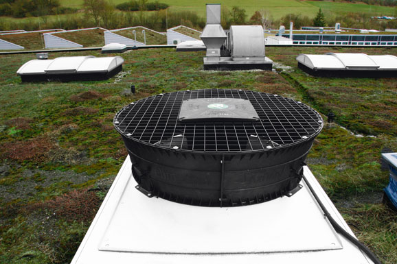
The inherent exit loss for fans with unimpeded airflow is often an underestimated energy guzzler. Figure 1 shows the power flow of the input drive power Po for an axial fan with unimpeded airflow. The drive power Po is split into static blower output (Pus = product of the air flow and static pressure increase of the fan), which is of use to the user, and various losses caused by the conversion into this useful power. The largest loss factor in the process is the dynamic output component (Pud) of air performance, which is also known as exit loss. This is made up of the product of air flow and dynamic pressure. The motor and fan manufacturer ebm-papst has now picked up this issue and has developed a new kind of diffuser, the AxiTop. Replacing the conventional guard grille of the fan by the AxiTop diffuser (Fig. 2) significantly reduces losses at the air outlet. Efficiency increases while operating noise is reduced at the same time. In principle, the diffuser works like a reverse nozzle, as follows:
Dynamic energy converted into static pressure

Figure 2: The AxiTop diffuser from ebm-papst provides for a significant improvement of efficiency and noise. Its pressure-boosting effect minimises exit losses and makes it easier to adapt the fan to commercially available heat exchangers
Every medium is only able to absorb a certain amount of heat energy for each degree Kelvin. The possible temperature difference and the amount of heat to be expelled define the cooling air flow required. This air volume has to be delivered by a fan through the heat exchanger under consideration. To do this, a pressure differential is necessary which is sufficient to overcome the flow resistance of the exchanger. Normally, the delivered air flows at high speed from the exit side of the fan and dynamic pressure (pfd) dissipates into the environment. Dissipation means that the kinetic energy of the flow is converted into turbulence and then due to friction into heat that is often no longer technically utilised. With the AxiTop diffuser, much of the dynamic kinetic energy is converted into static pressure (pfs) by way of retardation. Physically, this is easy to explain: The total pressure generated (pf) by a fan is the sum of the static pressure pfs and the dynamic pressure pfd_cges. In turn, taking the density r into account, the dynamic pressure can be split into three speed components (cylinder coordinates), the axial component pfd_cax=ρ/2*cax², the circumferential component pfd_cu=ρ/2*cu² and the radial component pfd_cr=ρ/2*cr².

Figure 3: The AxiTop diffuser allows part of the dynamic pressure to be converted into useful static pressure by retarding the flow
In the diffuser, the axial and circumferential components of dynamic pressure (ρ/2*cges²) are reduced due to the air slowing in the expanding cross section and, due to the conservation of energy (Bernoulli´s principle), the usable static pressure component increases (see Fig. 3). Efficiency can be significantly increased in this way if all components are co-ordinated to be aerodynamically optimised.
In practice, the use of the AxiTop diffuser does not just mean lower energy consumption; it also means greater degrees of freedom for the user and for the development engineer. The diffuser configuration can be optimised for different characteristics, depending on the application concerned. Either a greater blower output is possible with unchanged energy input, or unchanged air performance is possible with lower energy consumption. A diffuser can also greatly improve the noise behaviour. This acoustic improvement is especially interesting when fans are working is a noise-sensitive environment, for example in overnight operation in ventilation and climate control systems in residential buildings or in rooms where people meet and where there are also noise protection regulations to be fulfilled.
Significant potential to be exploited

Figure 4: Energy consumption and noise development are significantly lower with unchanged air performance. Blower output is increased and noise reduced with unchanged power input. (Details from an example application)
The potential of the possible energy savings, increased efficiency and noise reduction provided by an optimal diffuser is substantial for common heat exchangers on the market. This has been confirmed in extensive test series. Figure 4 illustrates a specific example. Replacing a normal fan with a guard grille with the same fan with a support bracket, guard grille and diffuser allows savings of 27 % for energy consumption while enabling an operating noise level 7.2 dB(A) lower with the same air flow (see Fig. 4).
Alternatively, if the greater efficiency of the fan with differ is exploited, it will deliver about 9 % more air flow with the same input power, and at the same time noise emissions will be reduced by 4.9 dB(A) (see fig. 4). This value has been determined on an exemplary customer application. Depending on the individual configuration, the optimised efficiency can be used either to reduce power input or to increase air performance. So not only does the user save energy during operation; the design engineer for a climate control system can get by with smaller heat exchanger surface areas. The space needed for the cooling unit can be reduced with unchanged or even improved noise behavior and constant refrigeration capacity. The reduction in the space needed is an argument which cannot be neglected, above all for larger heat exchangers. A diffuser is even worthwhile if it subsequently turns out that the system does not have a sufficient refrigeration capacity, e.g. in the case of a design error. It enhances the air performance without increasing noise. In such cases, the installation of an additional heat exchanger (and the associated costs) can often be avoided.
Can be retrofitted and used in existing wall rings

Figure 5 (right): The thrust range is not affected by the AxiTop diffuser. The illustration shows the axial flow rate with diffuser on the left and without diffuser on the right
Equipping existing heat exchangers with a diffuser is easy and only requires a few changes to ventilation and air-conditioning units. The diffuser is fitted in place of the guard grille. Existing wall rings can still be used. The AxiTop diffuser from ebm-papst is just 250 mm high so it needs very little space.
With these dimensions, the development engineers have succeeded in achieving a very good compromise. Physically, a diffuser cannot be large enough in order to increase static pressure. But dimensions which are as compact as possible are required in practice. CFD simulations combined with parametric optimisations have produced an excellent aerodynamic result. The change in the outflow profile causes the flow to split slightly, enabling the thrust range of the fan to be maintained. Figure 5 shows the different characteristics of the exit speed cax, which is of relevance for the thrust range, with and without a diffuser.
The new AxiTop diffuser is designed for fans of the sizes 800 and 910. Versions for 500 which are frequently employed with heat exchangers will follow in the near future. It doesn´t matter whether the fan works with EC or with an AC drive. However, in the interest of energy efficiency, the combination with EC fans in certainly preferable.
Leave a comment