Tracking down sound sources in fans is not an easy task. Whereas relatively advanced aerodynamic simulation programs are now available and have become established on the market, the simulation of aeroacoustics is still very much at the research stage. The number of cells needed for the required spatial resolution of small turbulent structures is far higher than in the case of aerodynamic simulation. For a fan in particular flow situations the figure may even be as high as tens or hundreds of millions.
Another necessity is high time resolution – typically with intervals of around 10 microseconds. This demands great computational resources and the associated time and financial outlay. That explains why, in the case of fans for example, only the larger turbulent structures (of relevance to acoustics) are resolved. Even with these limitations the outlay is considerable, and work is currently in progress to find ways of reducing the amount of computational work involved. Experimental processes are helpful in this regard.
Beamforming with microphone array
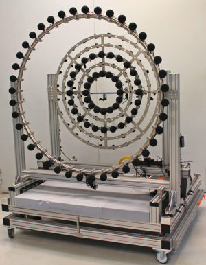
Figure 1: The circular microphone array with 80 microphones arranged on two levels is used on the intake side of the fan test stand.
One example of an experimental method of localizing sound sources on a rotating fan used by the ebm-papst motor and fan specialists to supplement complex aeroacoustic simulation is the so-called beamforming process. At the heart of this is a circular microphone array (Fig. 1) with 80 microphones arranged on two levels.
The microphone array is used on the intake side of the fan test stand to measure the differences in propagation time of the sound waves to each of the microphones. Sophisticated algorithms then evaluate the data obtained over a period of 30 seconds at a known fan speed. The results show that the beamforming method detects the same trends as aeroacoustic simulation (Fig. 2). The experimental findings thus also permit checking and optimization of the numerical simulation.
For localizing sound sources ebm-papst uses the so-called beamforming process as a supplement complex aeroacustic simulation.
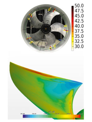
Figure 2: The beamforming method (above) detects the same trends as aeroacoustic simulation (below). In both cases the red areas show loud noise behaviour.
The evaluations reveal two dominant sources of noise for a typical axial fan: the tip gap flow between blade and fan housing and the so-called inflow turbulence (Fig. 3). At the tip gap, the difference in pressure between the outlet and intake sides causes air to flow over the fan blades at the blade tip. The flow interacts with the edges present there, in other words the blade surface and the surrounding housing wall. Vortices form which can increase the sound level by up to 10 dB on separation.
Inflow turbulence is particularly an issue when the fan is enclosed. A box such as those used for heat exchangers, for example, was chosen for testing with the microphone array. Backflow areas with corresponding circulation, in other words air turbulence, occur at the housing walls. This is then drawn towards the points at which the gap between fan and housing wall is at its narrowest. The turbulence from both sides merges here.
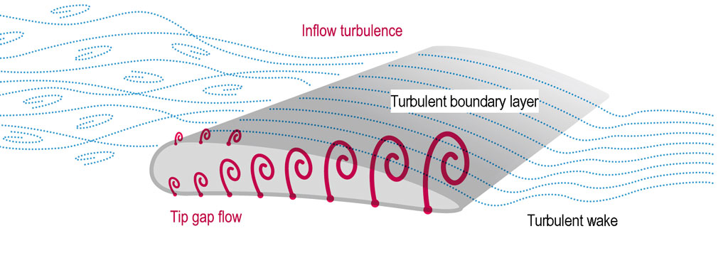
Figure 3: The noise level is increased by inflow turbulence and the tip gap flow. Inflow turbulence is particularly an issue when the fan is enclosed.
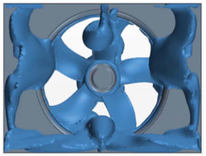
Figure 4: Vortex strings in a box-type inflow situation.
These “vortex strings” then produce great turbulence (Fig. 4). As a result, considerable fluctuations in pressure and velocity occur at the front edge of the blade, resulting in sometimes dramatic additional noise in the low-frequency range in particular. This takes the form of both broadband noise and narrow band tonal sound components, also known as blade passing noise. Everyone has at some point come across the unpleasant “humming” noise typical of this.
From finding the cause to tackling the noise
Once the sources of noise have been localized, action can be taken to improve the aeroacoustics of the fans: The size of the gap between the blade tip and fan housing was found to have a considerable influence on noise behavior. The noise level decreases with a smaller gap, but production-related necessities mean that the gap dimension cannot be reduced beyond a certain point because of the risk of the blade tip catching on the fan housing.
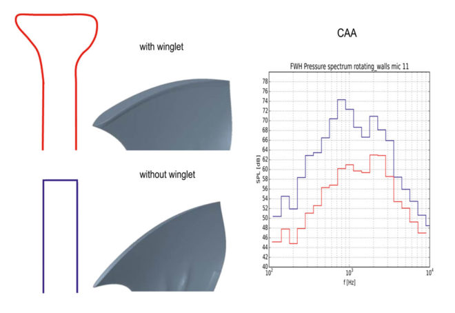
Figure 5: Winglets (red) added to the blade tips influence the tip gap flow and the vortices that form and so significantly reduce the noise level.
This is where winglets can help. These curved end caps added to the blade tips influence the tip gap flow and the vortices that form and so significantly reduce the noise level (Fig. 5). This has a positive effect on the tip gap flow, thus reducing the interaction of the flow with the edges. The sound power drops by up to 10 dB as a result.
Improving the inflow of the air to the fan lessens turbulence and thus also the low-frequency noise.
Geometric modifications to the fan alone are however not sufficient to reduce the inflow turbulence, as this results from the installation situation. Additionally insulating the housing tends not to be particularly successful either, as the insulation panels used normally only take effect as of higher frequencies. A different approach is more promising: Improving the inflow of air to the fan lessens turbulence and thus also the annoying low-frequency noise it generates. For this purpose ebm-papst has developed a special air inlet grill (FlowGrid) that acts like a flow straightener on the intake air. It thus dramatically reduces noise-generating disturbance in the inflow and is equally effective with both axial and centrifugal fans (Fig. 6).
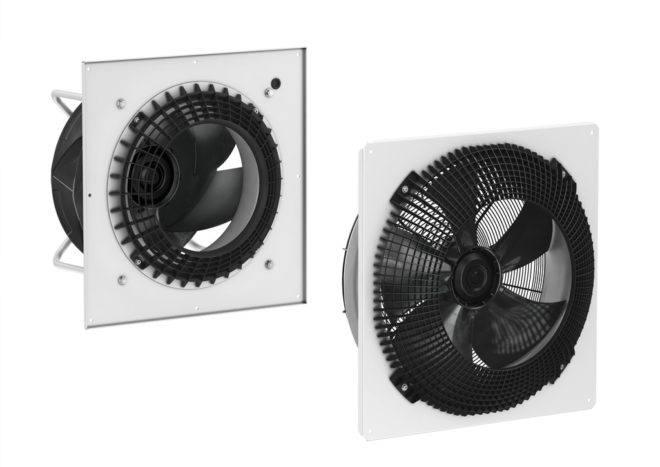
Figure 6: Regardless of the structural conditions and the installation situation in the housing, fans with an air inlet grill (FlowGrid) attain noise values comparable with those for operation under laboratory test conditions.
Regardless of the structural conditions and the installation situation in the housing, the fans then attain noise values comparable with those for operation under laboratory test conditions. Aeroacoustic testing has thus proven its worth as a means of optimizing fans. It will be interesting to see what the future holds in store. One thing is certain, energy-efficient fans from ebm-papst will become even quieter still.
Leave a comment