Constantly improving insulation in buildings is accompanied by increasingly refined solutions for room ventilation. Today controlled ventilation systems with heat recovery are used with increasing frequency. The used but warm air from the interior is routed with a fan through a heat exchanger to the outside, while cool fresh air is brought in from the outside via this heat exchanger and warmed up. This minimizes heating losses and reduces the amount of required electrical energy.
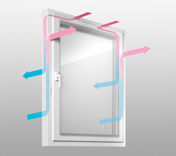
Active or controlled ventilation systems can be designed as centralized or decentralized systems. In the former, a central system distributes the air via ducts throughout the house; in the latter, each room is supplied independently of the others. The devices used in decentralized systems are much smaller and can be integrated in a building’s existing structure. A particularly elegant solution is to integrate the fan, the heat exchanger and the control electronics directly in the window frame (Figure 1). This was the approach taken by REHAU in the development of its GENEO INOVENT window fan in cooperation with the fan specialists at motor and fan manufacturer ebm-papst.
Requirements for fans and air duct design
Such a solution imposes special requirements on fans and air duct design. The conflicting aims of achieving the required air flow with compact dimensions and low noise emissions need to be reconciled. In the case described here, the fans from ebm-papst were specially designed to meet the conditions of REHAU’s GENEO window system. The available space in the window frame made it necessary to design for two separate fan-heat exchanger systems for air intake and exhaust instead of a single system with a bulky counterflow heat exchanger. The fans were designed using modern 3D flow simulations, first for the fans alone, later together with the window frame components relevant to air flow.
Fan, heat exchanger and control electronics are integrated in the window frame.
Special use for cylindrical rotor fans
For this task newly designed compact centrifugal fans from ebm-papst were chosen, so-called Sirocco fans, sometimes also called squirrel-cage fans. These DC fans have electronically commutated drives with electronic reverse polarity protection. The electronics are integrated in the fan’s impeller hub to save space. The outstanding efficiency of the brushless drive results in lower heat stress for the bearings, which increases the service life of the fan. The air flows in through a round inlet orifice, is radially deflected inside the fan and leaves it through the tangentially positioned outlet. Sirocco fans are characterized by a high number of blades that are bent in the direction of rotation. The blades transfer the rotational energy to the air flow while the static pressure increase takes place in the spiral. Without the spiral the air would simply be mixed. Due to its design principle, this fan type has highly turbulent air flow with lower aerodynamic efficiency compared to other centrifugal fan designs. On the other hand, the high number of blades is beneficial as it results in lower noise emissions with fewer disturbing tonal components. Today, fluid mechanical calculations for centrifugal fans with forward-curved blades are possible with modern simulation methods. Using numerical flow simulations, the complex air flow structure in the fans can be computed and the results are used to optimize the fan geometry with respect to the application.
Three-step fan design
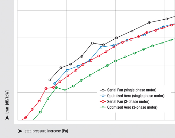
The fan design took place in three steps. In the first step, a low-vibration electronically commutated three-phase motor was integrated in a fan with similar dimensions (Figure 2). This drive ensures minimal generation of the structure-borne noise that is often considered disturbing at low speeds. In the second step, the aerodynamic components (scroll housing), number of blades and blade angles) were designed using 3D flow simulations and related experiments. Figure 3 shows the fan’s overall sound power plotted against the back pressure of the flow channels through the window frame.
With increasing air flow through the flow channels, the back pressure increases, thereby requiring a higher fan speed. Consequently, the values on the x-axis are also a measure of the fanspeed: the higher the speed, the greater the air flow, the higher the back pressure and the higher the sound power level. The black curve shows the behavior of the series fan with a basic single-phase motor. The blue curve denotes a fan with the same dimensions and drive but with optimized aerodynamics and the red curve shows the acoustic behavior of the series fan when equipped with a three-phase motor.
Improvements to aerodynamics and motor
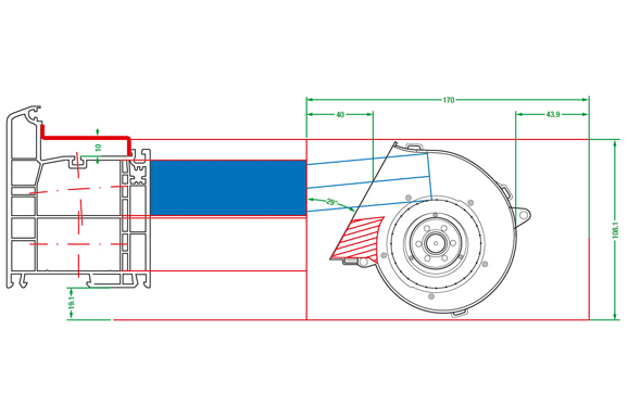
It can be seen that improvements in aerodynamics are just as effective as choosing the right motor technology. For pressures above 90 Pa, both effects can be approximately added without negative interference, so both improvements were used in the new fan. The fan dimensions were further reduced and adapted to the geometrical requirements of the application (Figure 4).
Thanks to the easy window replacement the building suffers no negative visual impact.
Further optimization with CFD
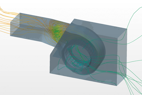
Since the fan cannot be operated under optimum intake and outlet conditions, the actual conditions of installation have to be included in further optimization efforts. For this purpose, computational fluid dynamics (CFD) is a very effective method. The relatively large effort involved in performing CFD calculations enables the simulation of complex flow processes in a unique way (Figure 5). Effective visualization of the results helps in assessing modifications and improvements so the amount of experimentation can be reduced considerably. To integrate the system into the window frame, two fans with identical aerodynamics and motors but different directions of rotation are needed: a clockwise fan for the intake and a counterclockwise fan for the exhaust.

Figure 6: Air performance and sound power of centrifugal fan with point of operation and aerodynamic resistance curve for window frame.
With respect to air performance and noise emissions (shown as sound power), the fan operates close to its acoustic minimum. Regarding the scale of the red curve in Figure 6 the deviations are well within measurement tolerances and product variations.
Decentralized residential ventilation systems integrated in window frames provide the convenience of fresh, preheated air. Thanks to the easy window replacement without extra installation effort, the building suffers no negative visual impact. The window’s functions of noise suppression and protection against break-ins remain in effect. To fully achieve these benefits, ebm-papst developed especially efficient and quiet fans with a design optimized for the limited available space in window frames.


can’t open my windows all the time because I have pets, but I also need fresh air. This is a great solution for people in higher levels