
The efficiency requirements for fans have been set out since 2013. They were raised in 2015, and there are plans to raise them again in the near future. The effects of the regulation have become impossible to overlook as energy-efficient EC fans are strengthening their position on the market, reducing CO2 emissions and benefiting the environment. In addition to energy-efficient motors, aerodynamic improvements are primarily responsible for the high efficiency levels of the modern fans.
Proper evaluation of a fan’s efficiency means testing the fan as it will later be used. Otherwise it – and any equipment it is installed in – may not bear the CE marking. There are good reasons for this. Any slight modification, for example in the design of nozzles or support struts, affects the fan’s efficiency and thus its ErP conformity.
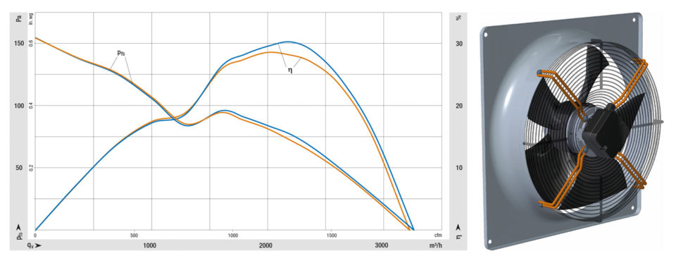
Figure 1a: Effect of operating conditions on fan efficiency: HyBlade with support struts (orange) and HyBlade without support struts (blue). (Graph | ebm-papst)
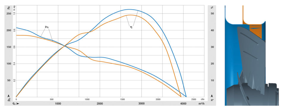
Figure 1b: Comparison of axial fan with complete fan housing (blue) and axial fan with short nozzle (orange). (Graph | ebm-papst)

Figure 1c: Ideal installed position (orange) and nozzle shift of 20 mm, blue and green in opposite directions. (Graph | ebm-papst)
Support struts cause unavoidable blockage of the air flow at the intake or outlet, resulting in efficiency decreases of a few crucial percentage points depending on the operating point (Fig. 1a). Nozzle geometry has similar effects, even when the air gap remains unchanged (Fig. 1b). The efficiency also decreases by a few percentage points when an axial fan is operated in a short nozzle instead of a full nozzle. The position within the nozzle is also crucial; an axial shift of a few millimeters can result in efficiency losses (Fig. 1c).
Those wanting to be on the safe side with regard to the fan regulation should therefore select solutions whose energy efficiency has been determined in exactly the conditions under which those solutions are ultimately to be used (Fig. 2 and text box). Otherwise the users must prove ErP conformity themselves. Motor and fan specialist ebm-papst has a wide range of fans which, thanks to GreenTech EC technology and optimized aerodynamics, not only satisfy but substantially exceed the requirements of the ErP Directive.
Thanks to GreenTech EC technology and optimized aerodynamics ebm-papst fans exceed the requirements of the ErP Directive.
If one wishes to optimize a fan’s efficiency, one must examine the aerodynamic loss mechanisms with an eye to reducing them. In axial fans, losses typically arise at the gap between the rotating impeller and the stationary fan housing. Possibilities for improvement are rapidly exhausted since the gap will always have a certain size for manufacturing reasons. In addition, there are turbulence losses that arise due to differences in flow speed and losses at the outlet.
In centrifugal fans, gap losses arise because some of the air is transported in a circle through the nozzle gap. There are also pressure losses at the blades, which do not receive optimum air flow in all areas. For both fan types, the greatest potential for improvement is in the outlet, where high outlet speeds lead to losses as the speed and thus the dynamic pressure go unused.
Guide vanes and diffusers
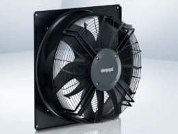
Figure 2: Fully assembled AxiBlade fan with fan housing, guard grill and guide vanes.
Much can be achieved by the use of guide vanes or a diffuser on axial fans. Since the rotation of an axial fan’s impeller imparts angular momentum to the expelled air, attaching stationary guide vanes results in a static pressure increase as the kinetic energy conveyed by the angular momentum is converted to static pressure. Diffusers externally mounted at the outlet side offer a means of minimizing outlet pressure losses in larger axial fans. In practice, use of the AxiTop diffuser from ebm-papst enables lower energy consumption and greater freedom for engineers and users. For example, the diffuser’s configuration can be optimized for various properties depending on the application. Higher fan output with the same energy input and lower energy consumption for the same air performance are equally possible. Acoustic performance can also be improved considerably with the diffuser.
Best possible efficiency at actual operating point
To ensure that the axial fans really work at the best possible efficiency level when installed and operated at application-specific operating points, the AxiBlade series was developed; its axial fans operate in a wide range of applications at an efficiency of up to 54% with respect to the static pressure increase. At the same time, the noise level can be reduced by up to 8 dB(A) compared with the standard range by increasing the diameter while maintaining the same space requirements as the industry standard and using a modular design; depending on the required pressure ranges, the fans can be combined with guide vanes. Further features include impellers with profiled blade geometry and winglets to minimize noise. The impellers are specifically designed for the different motors with which they can be combined, which also increases the efficiency.
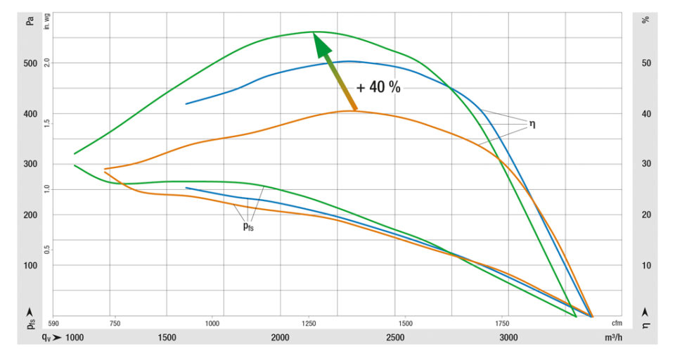
Figure 3: Diameter increase at constant dimensions reduces outlet losses: comparison of HyBlade (orange) with AxiBlade without (blue) and with guide vanes (green). (Graph | ebm-papst)
In this way, the axial fans can be optimally designed for a particular application, with an efficiency increase of up to 40% compared with the proven HyBlade series. The version without guide vanes is suitable for low to middle pressure ranges – up to 200 Pa for the axial fan depicted in Fig. 3. In this case, the benefits of the guide vanes do not come into play. Even without them, the efficiency and operating noise are much better than the current industry standard. Guide vanes are essential at high back pressures of up to 260 Pa in order to reach high efficiency.
Since the footprint of these axial fans corresponds to the current industry standard, virtually no design changes to customer equipment are necessary. And the fans require lower spaces than the usual models. Their height is likely to play a minor role for most applications, but not for transport. Every centimeter counts when the fans have to be loaded onto pallets or into containers.
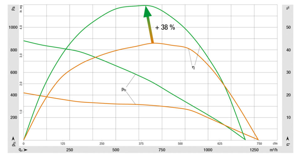
Figure 4: Centrifugal fan in scroll housing (green) for increased pressure generation and efficiency compared with a centrifugal blower (orange). (Graph | ebm-papst)
A centrifugal fan with scroll housing
With a view to the increasingly strict requirements regarding the efficiency of ventilation equipment for residential buildings, ebm-papst has aerodynamically optimized its proven RadiCal centrifugal fans.
To further reduce outlet losses, the fans can be combined with a scroll housing that has also been aerodynamically optimized. The scroll housing has an outlet with a round cross section for direct attachment to the pipe fitting on the unit’s air outlet. This considerably reduces the usual turbulent flow losses. At the same time, the characteristic curve becomes very pressure-insensitive, and the efficiency increases by up to 38% compared with centrifugal blowers of the same design (Fig. 4). In addition, the noise level decreases by 3.5 dB(A). These fans are also available in a volume-flow-controlled design with a vane anemometer for extremely precise control.
For users, this makes it easy to be on the safe side of the ErP Directive without great effort for both centrifugal and axial fans. Aerodynamic optimization improves efficiency and noise characteristics, even in extremely different installed configurations.
The EU has finally defined the fan
There were previously many gray areas in the fan regulation. For example, it was long unclear what minimum configuration a fan subject to the regulation should have and how it has to be evaluated in terms of energy. The principles for determining efficiency were thus insufficient for manufacturers and market regulators.
The new EN 17166 standard, expected to take effect at the beginning of 2020, will eliminate the gray areas and establish a reliable foundation for ErP assessments. A fan always consists of “significant elements” that contribute to the conversion of electrical or mechanical power into pressure and air flow. These include the rotor, i.e. the impeller, and the stator, which consists of the housing, inlet ring, fan housing, etc., and the motor.
Of fundamental importance is the requirement that the fan always has to be evaluated as it will later be used in order to rightly bear the CE marking, because the motor and the entire flow machine always determine the efficiency.
Leave a comment